

(*) Ersatz: replacement product.
Replacing an A409 triode
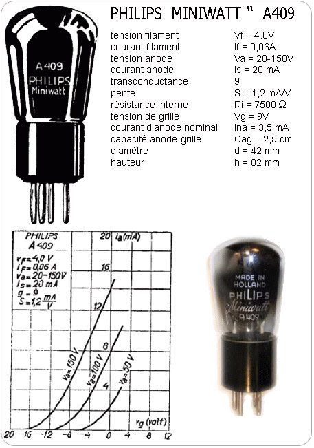
Triode tubes for battery-operated radios date back to the 1930s.
Tubes such as the A409, A410, A415, etc., are hard to find and/or often
unusable. While waiting to find replacements, the radios remain silent.
One can therefore try to temporarily replace them with more modern tubes.
Examining the tube's datasheet suggests that it can be replaced
by a number of other tubes.
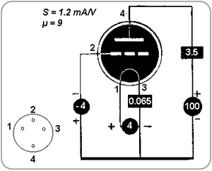
Substitution example
(Source: JC Jardine)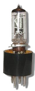
The "Miniature - 7-pin - battery" series from the 1950s may
be suitable (DK92, DF91, DL95... = 1AC6, 1T4, 3Q4...).
These tubes, which were used in portable receivers, are still available at reasonable prices.
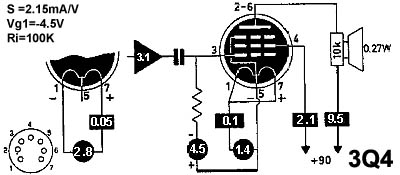
The comparison table below regarding anode current and voltage indicates that the DL95 (or 3Q4) tube is suitable.
The 3Q4 pentode will be wired as a triode. To do this, the plate and screen grid will be connected together.
The remaining tasks are to convert the base connections and adapt the heater filament voltage. Paradoxically, this is the only technical difficulty.
These tubes, which were used in portable receivers, are still available at reasonable prices.
The comparison table below regarding anode current and voltage indicates that the DL95 (or 3Q4) tube is suitable.
| Heater Voltage (V) |
Heater Current (mA) |
Anode Voltage (V) |
Anode Current (mA) |
Bias Voltage (V) |
Transconductance (mA/V) |
|
| A409 | 4 | 65 | 80 | 3.5 | -9 | 0.9 |
| 3Q4 | 2.8 | 50 | 90 | 7.7 | -4.5 | 2 |
The 3Q4 pentode will be wired as a triode. To do this, the plate and screen grid will be connected together.
The remaining tasks are to convert the base connections and adapt the heater filament voltage. Paradoxically, this is the only technical difficulty.
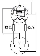
To lower the heater voltage from
4 V to 2.8 V (a drop of 1.2 V) at a current of 50 mA, a resistor is placed
in series with the filament:
R = 1.2 / 0.050 = 24 Ω ...is therefore necessary.
This resistor will be distributed across each filament terminal. We will therefore place a 12 Ω (1/4 watt) resistor on each filament terminal.
The DL92/3S4 tube (same pinout, same heater) is also suitable.
R = 1.2 / 0.050 = 24 Ω ...is therefore necessary.
This resistor will be distributed across each filament terminal. We will therefore place a 12 Ω (1/4 watt) resistor on each filament terminal.
The DL92/3S4 tube (same pinout, same heater) is also suitable.
