

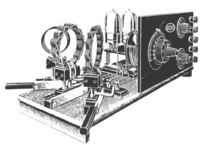
Battery-operated radio sets used during the 1920s required up to five DC voltages:
+4V |
heating the tube filaments |
-12V |
grid bias (variable from 0 to -12V) |
+40V |
supply for the screen grids of tetrodes and for the plates of low-voltage tubes (A441N) |
+80V |
high-voltage plate supply |
+120V |
loudspeaker field-coil supply |
To power a seven-tube radio set with some reserve power, the following currents must be supplied:
| 4V | -12 to 0V | 40V | 80V | 120V |
| 1A | 0 | 5 mA | 50 mA | 20 mA |
Solutions
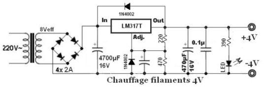
4V: This is the critical voltage. Since exceeding it could burn out these rare and expensive tubes, regulation using an LM317T will be chosen. A 4700µF filter capacitor will result in a 2V ripple voltage, so the peak rectified voltage must be at least 7V. The secondary voltage of the step-down transformer must therefore be at least 7/√2, i.e. a minimum of 6Vrms.
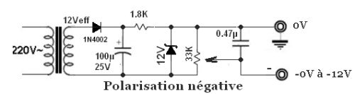
-12V: this source supplies no current. Half-wave rectification followed by regulation using a Zener diode will be sufficient. The Zener diode will draw ≈ 2 mA.
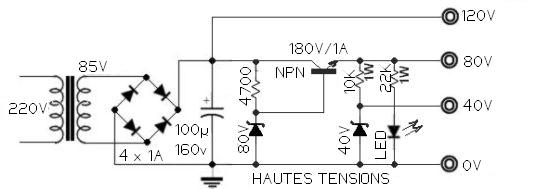
40V: this source will be derived from the 80V supply using a Zener diode (~ 2 mA).
120V: this source requires neither regulation
nor extensive filtering. It will feed the 80V regulator. The RMS voltage
of the step-down transformer's secondary winding should be approximately 85V.
80V: this 'High Voltage' supply must be filtered and
stabilised. A series regulator circuit based on a power transistor (or MOSFET)
will therefore be suitable.
A 25VA transformer must therefore provide 85V/0.1A — 8V/1.5A —
12V/5mA. Small separate transformers may also be used.
High-voltage supplies
4V supply
Negative bias supply
Practical construction
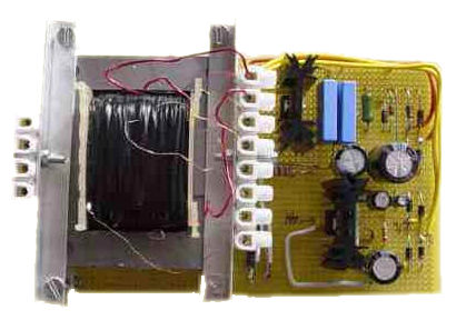
("
For the record, I used components I already had on hand, as follows:
- The transformer was recovered from a Jouef transformer. The iron core cross-section corresponds to a 40VA transformer, and its no-load output voltage was 18V. It could supply 2A. I then unwound the secondary winding, counting the turns in order to determine the number of turns per volt—in this case, 7 turns per volt. I then rewound three secondary windings to obtain 85V (595 turns of 0.2mm diameter wire), 12V (84 turns of 0.2mm wire) and 8V (56 turns of 0.8mm wire).
- In the photograph above, the NPN transistor and LM317T can be seen, both housed in TO-220 packages and mounted on heat sinks.
- The 12V Zener diode dissipates less than 25mW.
- The 40V and 80V Zener diodes each dissipate less than 1/4W. They may be made up of several Zener diodes connected in series.
